2018-08-24
2018-08-25
Note: This post a bit of a mess because I kept screwing up and being wrong. I am going to leave it this way because I don’t want to have yet another ‘highlight reel’ of an Internet presence. Learning is a messy endeavor, especially when you’re not some brillient mind that “just gets it”.
The impetus behind the last revision of the board was current. Specifically current handling. More specifically issues with current handling. Even more specifically uncontrolled inrush currents. This inrush current caused problems for the power supply at board power-up and for the IO board at analog peripheral power up. See here and here for more details. In this this post we’ll explore these inrush currents.
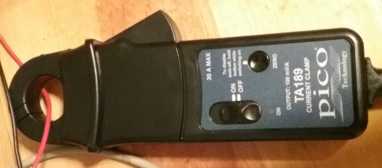
In order to put some numbers on the currents I bought a Pico TA189 clamp probe. The reason I chose this particular probe is due to its output range and ability to measure low currents. Many current probes in this price range will only claim to go down to 30mA for example. I will do a more detailed writeup of the probe some other time, but sufficient to say it did what I needed it to do – to show me the current form on startup.
The potato cam is back:
So what are we trying to see? We’re trying to see what’s happening with the current as a capacitive load is slammed on. Now while I did not take into account the turn-on current of the large capacitive load that is the combination of the the board(s) and their peripherals, the real world is such that current limiting resistors are not only plentiful, but unavoidable. Every wire, every trace, every terminal is a resistor. The janky cable I’m using to connect the board to the power supply, the kind with the rotating banana plug on one end, is upwards of a couple of Ohms depending which part of him self Neal (the dog) is licking at a given moment. Not to give away the plot too much, let’s call it foreshadowing, bad connections will come into play in this post sooner rather than later.
A bit of a sidetrack. As I was working on this investigation I was underwhelmed by what I was seeing. Yes there was a current spike on power on, but nothing as severe as I had expected. Certainly nothing like what I guestimated in this post. Then it hit me like a current spike. When I was having the issues the board was being powered on by my Beaglebone power and serial board. See here for background. When I was experimenting with the current probe I was turning the power to the board on and off via the button on the bench power supply. The power and serial board turned the power to the board on and off via a relay. The bench power supply is a soft-on!

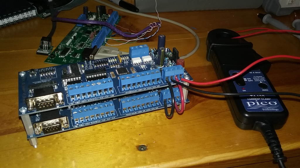
Gratuitous shot of the setup. We’re only testing the power-on characteristics so nothing is connected to the boards. I’m using two of the previous revision boards because the issues manifested with these boards.
Below are three initial shots of the current curve when the board is powered on.
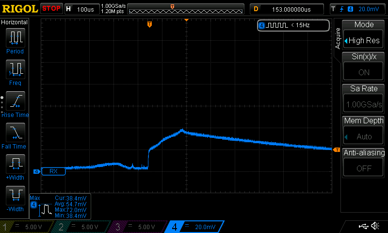
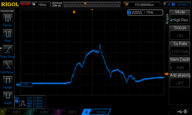
They look a little goofy don’t they. Lumpy like my mashed potatoes. Mashed potatoes are supposed to be lumpy, but current curves are not. Well not in this case anyways.
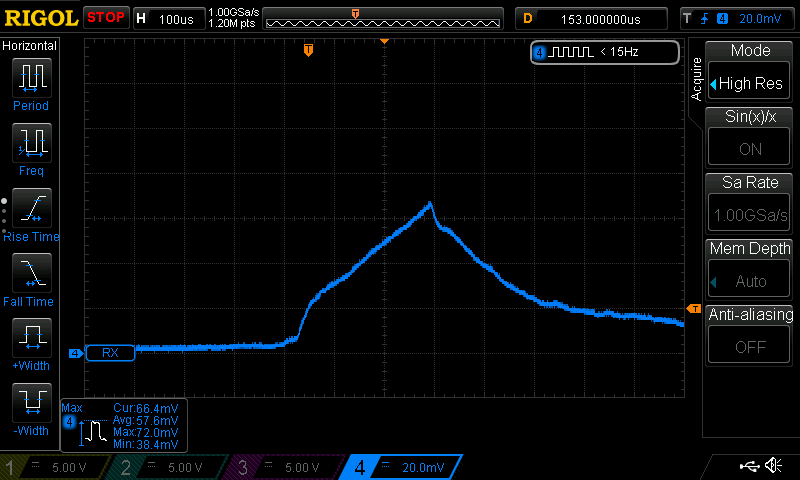
Anyways the problem turned out to be a … drum roll please … loose wire on the board’s power terminal! With that excitement out of the way here are a few shots with the terminal tightened down. Looks much smoother and repeatable.
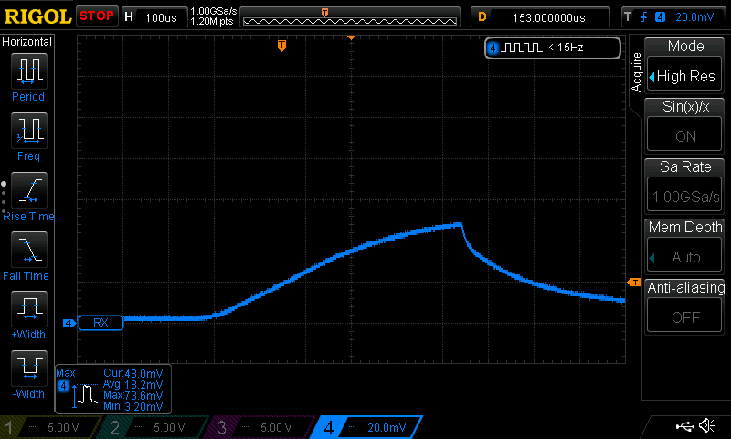
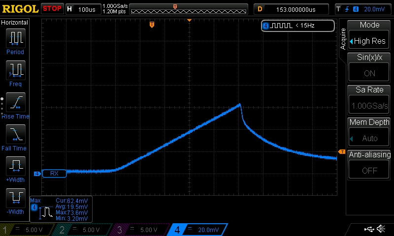
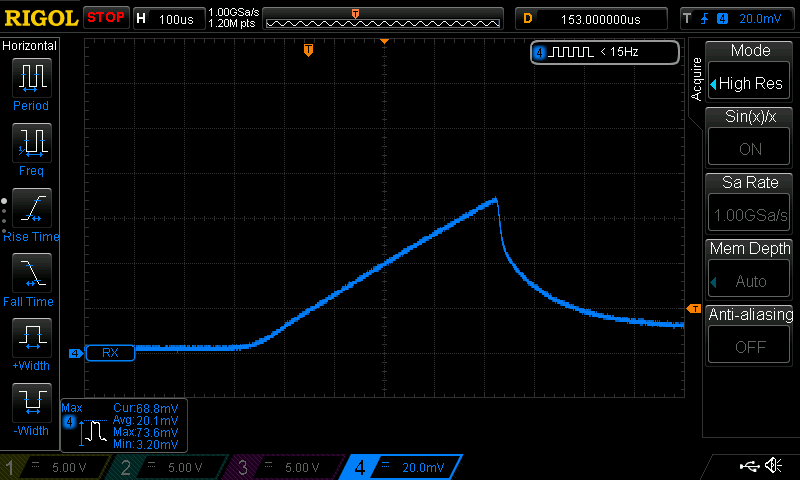
The average maximum current draw between the three shots is (48.0mV + 62.4mV + 68.8mV)/3 = 59.73mV. The current probe puts out (heyo!) 100mV/1000mA so the average maximum current draw is 59.73mV/100mV or 0.5973A. Certainly something, but nowhere near the 12A that I predicted. So that means that I was wrong then or that I’m wrong now.

In the previous post I estimated the board to have a capacitance of 220uF. I was wrong by a lot. I know this because I have two 180uF filter caps for the 5Vdc power supply alone. 220uF is the approximate total capacitance of the surface-mount capacitors only. If we include the large filter caps we’re north of half millifarad – 580uF. That’s quite a bit of capacitance to slam on with a relay. But we’ll get to that.
I’m sure right now you’re asking: but Vic, what is the relationship between the current draw and the voltage?! Good question. Here it is:
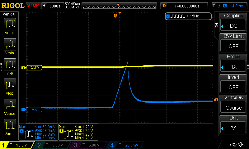
I had a good chortle at that one. But let’s get serious. Channel one is the 24Vdc input. Channel four is the current probe.
In this shot we see two current spikes. One right as the input voltage starts rising and another one as the input voltage approaches 10Vdc.
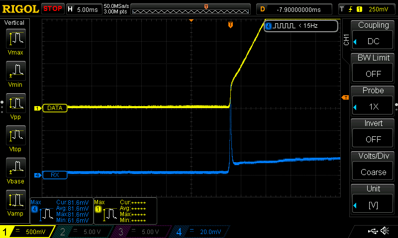
Here’s a 5ms zoom. As soon as the input voltage rises above nothing the initial capacitor charging starts.
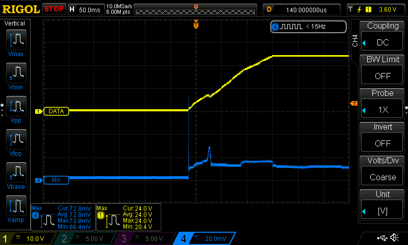
Another short with a larger time base for perspective.
Everything makes sense so far. As soon as there’s some positive voltage the capacitors start to charge. It’s important to note that initially only the capacitors hanging off of the 24Vdc power rail are charging. The capacitors on the 5Vdc power rail don’t start charging until the 5Vdc power supply comes on line. That’s the second hump in the third picture above. Here’s the detail. Channel two is the 5Vdc power rail.
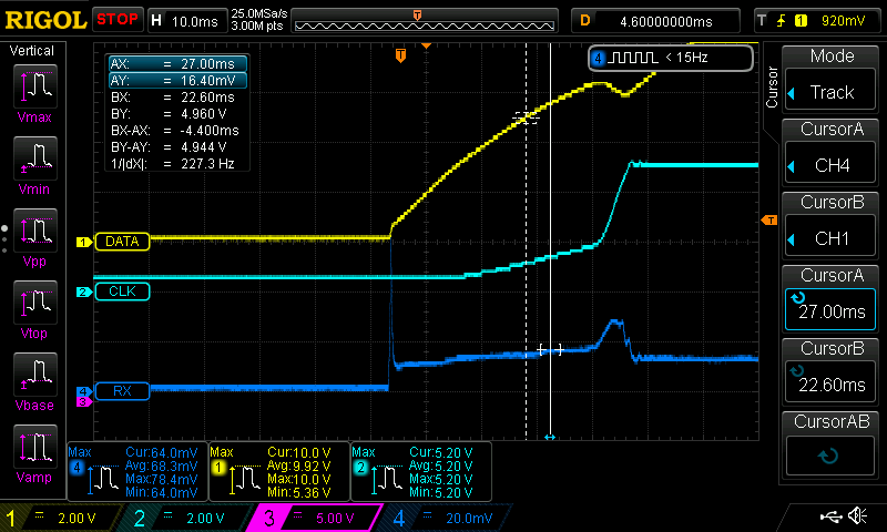
We can see that the 5Vdc power supply becomes active somewhere around 7ish volts.
So with the soft-on by the bench power supply we see the expected current spikes, but they’re not nearly as violent as we expected. This,on the other hand, is violence:
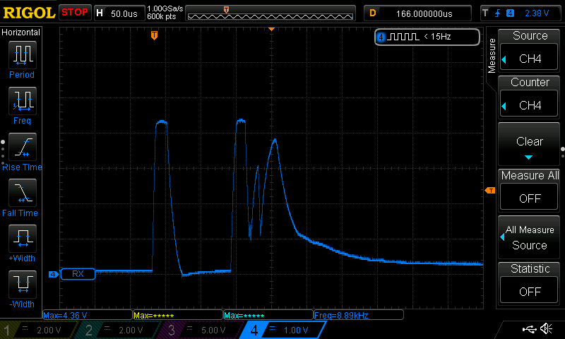
Let’s break this down. This is the current plot of turning the board on with a toggle switch. I turned the switch off. Enabled the output on the bench power supply. Turned the toggle switch on. I actually had to lower the bench power supply output to ≈18Vdc. Anything more would trip the over-voltage crow-bar circuit on the board. The maximum spike is 4.36V. The probe puts out 0.1V per amp, so 4.36V/0.1V = 43.6A. That’s right. almost 44 amps. Told you there would be violence.
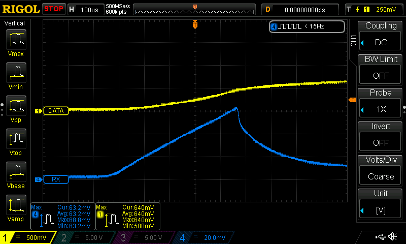
Here’s the zoom of the initial current spike:
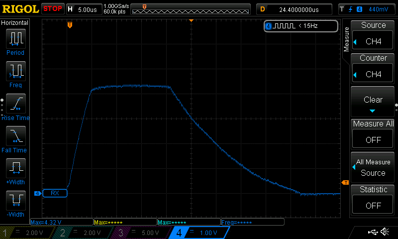
For 15uS my probe is clipping because it’s maxed out – it’s a 30A probe and according to the scope the maximum in that capture is 4.32V or 43.2A.
So there we go. That’s what an uncontrolled capacitive load looks like. It’s goal #1 to implement a soft-on on the Beaglebone power and serial board.