2017-12-30
2017-12-30
Note: I was wrong in the last post. It’s the dsPIC that has a broken UART, not the PIC24.
For the last month I have been doing the very unsexy work of grinding out bugs in the code. As I hinted at before my software stack had issues under load. I chose to test the full stack (hardware and software) by subjecting it to a completely unrealistic load. The logic behind it is that the board and its accompanying software stack is a relatively critical component. No lives depend on it, but you don’t want to have to constantly be rebooting your HVAC system. So if a system can gracefully handle an unrealistic load it can handle a realistic load (hopefully).
I loaded the board with a nonstop stream of requests from my workstation and everything fell apart. On the board the failures manifested themselves as buffer overruns. On the middle-ware the failures were incomplete and corrupt messages. I will not go into the very boring details, but here are the highlights:
- The code on the communications microcontroller is slow. The major mistake I made is relying too much on polling rather than relying on the interrupt mechanism to detect and handle changes in state. Rewriting the firmware is not really an option at this point as I wan’t to complete this project and put it into use. Next project will definitely use interrupts more.
- Related to the point above, the code on the microcontroller is too complex and convoluted. I tried to do too much at once with it. A human-targeted CLI and a binary machine protocol should have been combined into some sort of ugly middle ground. Right now the main event loop has a dozen or so conditionals. This translates to twice as many (very broadly speaking) branches in assembler. Then throw in a bunch of function calls which are also branches. Since a taken branch in the Microchip architecture takes at least two instruction cycles the result here is that the processor spends a lot of its time stalled. Again, a rewrite is not in the cards so we’ll have to get creative.
- The RS232 hardware flow control seems to be a suggestion at best. As verified with the oscilloscope, a flow control line going low does not mean that the other end will immediately stop sending data. Yes, the reality of physics: time and signal propagation delays can not be escaped, but c’mon. I really want to.
- The middle-ware code that talks to the board had a few very interesting bugs. They were kind of a pain in the ass to track down since the debugger situation on Linux frankly sucks. I ended up using DDD and it did the job, but it is embarrassingly anachronistic. The Motif(?) widget set that is utilizes is simply atrocious. I may be succumbing a bit to the ‘Golden Age Fallacy’, but I don’t remember the old Unixes (Unixen? Unixi?) having such a piss-poor interfaces and those were based on Motif.
So what has been learned from and what has been changed to fix the varied and numerous failures. One thing that has been thoroughly reinforced is that I am never wrong and do not make bad decisions. Everything is someone else fault. A partial list of things that have been changed in order to accommodate others’ shortcomings:
- Implement internet checksums of messages originating from the board. I implemented this as a way of ascertaining if the messages were being corrupted in transmission due to RS232 weirdness. Turns out no, no messages were corrupted in transmission. It was all my code that was corrupting data.
- Fixed bugs in the serial buffer assembly code in the middleware. This is what was corrupting the incoming data. It all came down to one ‘continue’ statement in a message assembly loop. That one statement made a loop counter advance by one and miss the next byte in the buffer.
- Changed the communications mode from pull to push. Originally the middleware would initiate a request for data from the board. I failed to get that to work reliably so I flipped the script. The board now pushes the data out to the middleware layer.
- I2C bus dead-lock. This is an interesting problem in a sense that it’s unbelievably fucking annoying. Once in a while, on the scale of a every few days, the chip to chip communication via an I2C bus ceases. The clock and data lines remain high, but one of chips believes that it saw something come down the line which puts it in a wait state that never ends. This is worth an entry of its own.
- Thread death monitor. I’m a firm believer of fail-fast system design. Especially in the multi-threaded code. During the stress testing of the system the serial board IO thread died occasionally due to a lock contention issue. I have implemented a monitor that restarts a serial IO thread upon its death.
- Modulo addressing of the command buffer. Everything – weeks of swearing and drinking – came down to this. The reason why the calibration binary protocol was failing to set reasonable values is because the serial receive buffer was wrapping around. Even though the receive code was wrapping the buffer, the read and interpret code was not. So if the binary protocol message to set calibration values was received at such a time as to cause the serial receive buffer to wrap around, the code reading the buffer failed to take that into account and would read values out of the memory outside of the bounds of the buffer. The reason why the calibration stuff triggered this bug is because its the largest message that the board receives. Most of the other messages the board receives are in the neighborhood of a byte or two. The calibration message is 16 bytes (8 analog input ports times 2 bytes per port) plus the protocol overhead.
That’s the adventures in software land. In hardware land everything is not rosy either. The name of Vic’s failure here is: current control. I have failed to take into account behavior of capacitive loads. If I remember correctly, I was kind of aware of the issues, but I hand-waved it away as something that could not possibly affect something as simple as a home-made IO board. Vic was wrong. Here’s the screen shot to illustrate the problem:
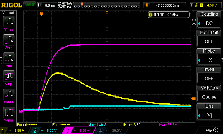
Channel three is the 24VDC power supply. Channel two is the 4-20mA temperature output from the measuring device. Channel one is the 4-20mA relative humidity output from the measuring device. Both 4-20mA channels are terminating at a 250 Ohm resistor. The issue here is that the analog input on the board is clamped to 5.something volts. Which means that the 13.8 volt spike is essentially causing a dead short as on startup as soon as the clamping diodes become forward biased because I have no current limiting resistors anywhere. The fix is more resistors, of course. Which means another revision of the board. Ouch my wallet.
Here’s a partial list of changes in the latest revision of the board:
- Resistors, resistors, and more resistors.
- Switched most components to surface mount. This is mostly due to cost considerations with regard to PCB area.
- Switched the RS232 transceiver from Maxim to TI. Again, Vic is penny-pinching. The Maxim transceiver is in the area of 4x more expensive than the Texas Instruments one and the main difference is that the TI one requires external capacitors.
That’s it for now. Coming up will more details on the capacitive load issues and board redesign.