2017-10-01
2017-10-01
Today I was working on my power and serial expansion board for the Beagle Bone Black. This board provides 5VDC to the BBB, breaks out the RS-232 ports, and sequences (or is supposed to anyways) the power to the RS-232 transceivers and the IO board. All that because the BBB can not have any power applied to any of its input pins until a specific pin goes high indicating that the processor has found its glasses and is able to see stuff.
Because the output pins on the BBB can’t really drive much of a load, the magic pin going high tickles the gate on a FET which turns on the power to my favorite SSR, the Toshiba TLP222A-2(F), which in turn turns on two PCB mounted relays. One of the relays switches 3.3VDC to the serial transceivers and the other relay switches 24VDC which is intended to supply a device of my choosing.
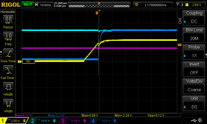
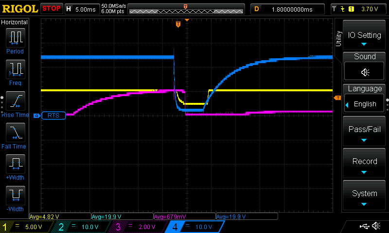
So I hook it all up and everything goes terrible super horrible. On power-up the BBB starts to strobe the magic enable pin. See scope shot below. Channel one is the 5VDC power supply, channels two and four are 24VDC rails, and channel three is the enable pin.
What we’re seeing here is everything going well until the enable pin goes high, immediately the 24VDC rail drops out, consequently the 5VDC power supply drops out, the BBB powers down, which causes the enable pin to go low, which restores 24VDC rail, which restores the 5VDC power supply, which causes the BBB to power on, which causes the enable pin to go high and the cycle repeats.
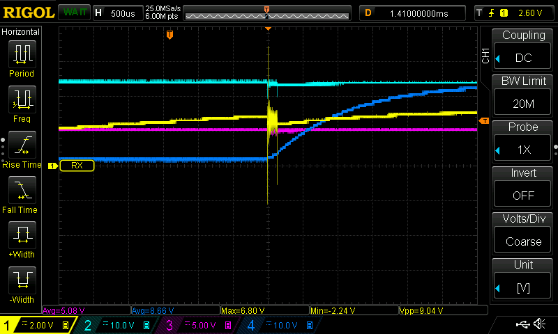
Here’s a close-up of the drama.
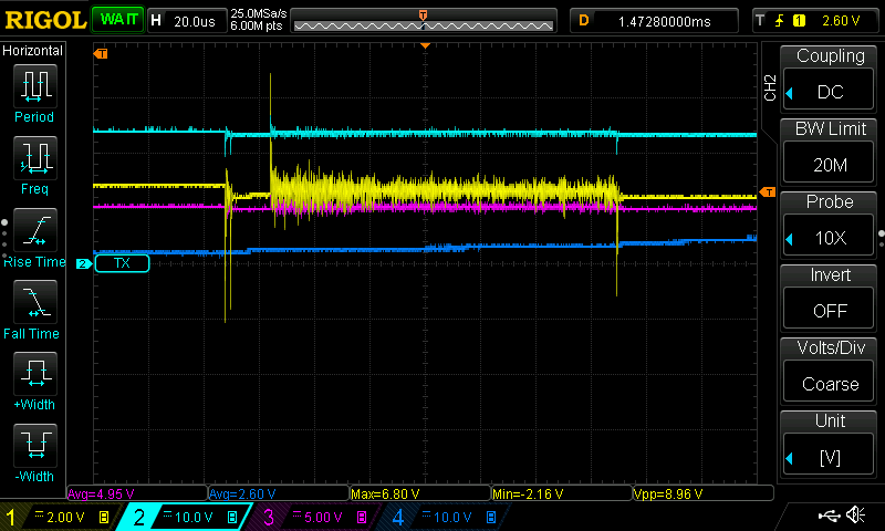
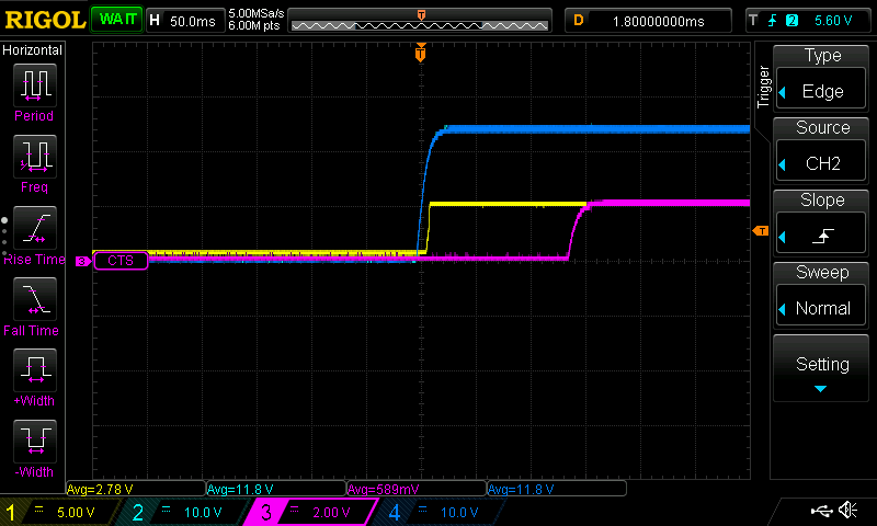
Below are two shots with the same settings of the sequence of operations without my IO board attached to the switched 24VDC supply. 24VDC supply turns on, 5VDC power supply comes online, the enable pin goes high, and everyone is happy.
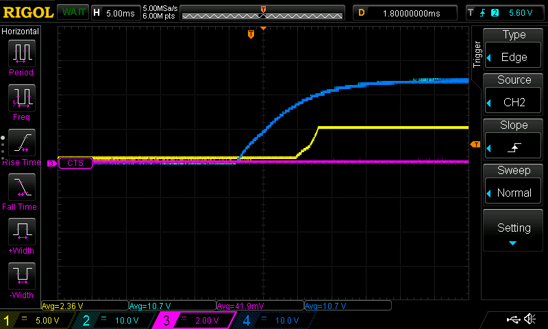
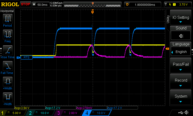
What turned out to be the issue is that my IO board has so much capacitance, that when the power to it is turned on rapidly by a set of relay contacts closing, it brings the 24VDC rail down which causes the cascade of issues. So what’s the fix. Well a current limiting resistor on the switched output does stop the 24VDC rail from being pulled too low. But it also creates a voltage drop which creates heat. A 100Ohm resistor completely fixed the problem, but it created a several volt drop and got quite hot. Currently I have a 5Ohm resistor as a current limiter and while it does prevent the above issue, there’s a nasty, approximately 10V, spike on the enable bin when the relay contacts close. See the three shots below.
In these channel four is the 24VDC input to the IO board. All other channels are the same – one: enable pin, two: 24VDC supply, three: 5VDC supply, four: switched 24VDC output. I’m thinking that the timing is very much in line with the noise appearing right as the relay closes and the 24VDC switched voltage starts to rise.