2017-05-31
2017-05-31
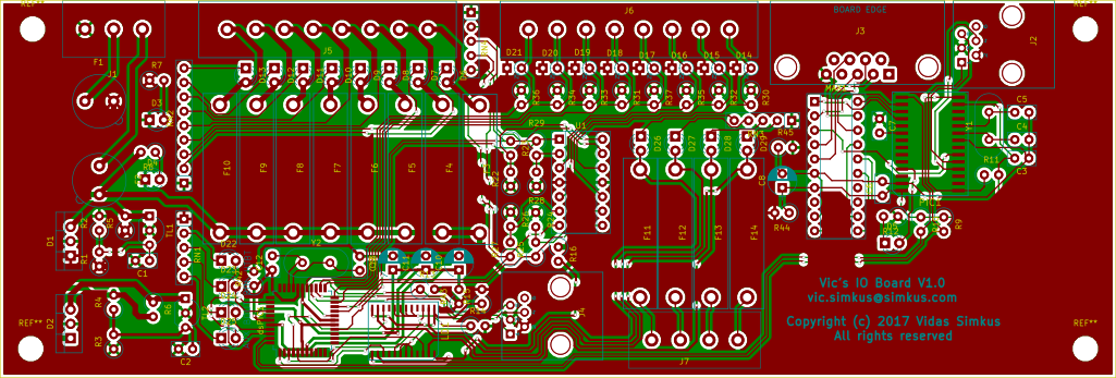
The board circuit design and schematic are done. This is pretty terrible picture export. I couldn’t figure out how (spent 15 seconds) to export an SVG of the board without the copper fills.
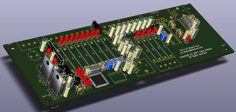
And here is the 3D rendering. A lot of 3D representations of components are missing, but the general gist is conveyed.
All of the design work was done using KiCad (http://kicad-pcb.org/) EDA. Which of course means that I had to learn KiCad. Too much learning with this project. It’s absolutely amazing to me what can be achieved using open and open source tools nowadays. I don’t think this level of personal productivity would be possible let’s say in the early 90s. KiCad, for all of it’s greatness, does suck in the user interface department. Their design philosophy seems to be “it was hard to develop, it should be hard to use”. I will say this, not once did it crash and lose data. I got some fairly gnarly error messages along the lines of “invalid pointer to mouse handler” or some such, but in never crashed. I did not lose any work due to KiCad crashing.
Certain design decisions for the board have been very deliberate. Yes, of course, functionality design was deliberate, but so was the “retro” look and feel of the board. I consider the board design to be very retro due to the preference to through-hole components versus surface mount. There are some SMDs, sure, but at this point that’s pretty much unavoidable. Over all though, the board is a throw back to the discrete component era. Everyone is falling over them selves to make their designs as small as possible. And from a MANUFACTURING standpoint that makes perfect sense. It costs a lot of money to have Joe bending and inserting resistor leads into a board versus a pick and place machine ripping little chips off of a reel and sticking them into solder at the speed of light. At a hobbyist level there are no such market pressures and thus I made a conscious choice to not be concerned about board space or assembly costs because my time is worthless (just ask my employer) and I’m willing to pay a little extra money for an extra square inch of PCB in a production run of quantity three.
I also made a conscious decision to use a lot of LEDs. Blinking lights are cool. That is a widely believed scientific fact. Modern technology does not have enough blinking lights. Modern devices have become boring in a sense. Yes you have a phone that can track your every move, secretly send all of your emails and voice conversations to nefarious third parties, take flawless pictures of your flawed life, immediate upload all your identifying information to “the cloud” in exchange for a virtual candy gemstone, but they lack blinking lights! Look at old technology, both real and imaginary, and they have dials, switches, and lights. Look at Start Trek (the good one – The Next Generation) and there’s all sorts of tactile interface and feedback and blinking lights. So my board has a lot of LEDs. They indicate fuse statuses, controller moods, and output statuses. Mode LEDs = more good.
Next step is sending the board to get made. I will have the board made, but assemble it myself. The plan is to go with OSH Park (link) for the fabrication. They are not the cheapest, but differ from most other fab houses in that they provide a graphical representation of their interpretation of your Gerber files and they farm out the work in the US. While I am certainly no Trumpite jingoist, it certainly makes sense to me to give business to a local (within the context of the country) establishment. There’s only so much fast food and other “services” we can sell each other.
I also tested the ICTD and associated circuit. I was very pleasantly surprised. My cobbled together circuit on a breadboard, using 1% resistors and an opamp IC based on fanboyism (squeeee Microchip!) was within 1C of my Cooper Atkins SH66A (link) at 0C, 100C, and room temperature.