2017-05-06
2017-05-06
Finally real progress is being made. The I2C communication stuff is working on both chips. I’m taking the register-based approach and have tested the implementation of all of the basic registers. Did a bit of stress testing on the communications stuff – weird input, input overflowing buffer sizes, collisions, and etc. and everything seems to be working fairly well in a sense that there’s no corruption, the failures are predictable and graceful, all data gets to where it’s supposed to be going.
The ICD3 came in just time. As in I had basically troubleshooted most of the issues before it got here. But it is a very nice piece of gear. Debugging is super nice and fast. But, BUT, I was wrong. Make note. 2017-05-06 Vic was wrong. I thought that having it would allow me to use different pins for programming and debugging, but I was wrong. You can reassign debug pins (EMUC/EMUD), but not the PGC/PGD pins. And if you reassign the debug pins, you need a special adapter. I guess I should have read the literature more attentively, but hey, I needed (read: wanted) a more “professional” tool to do the chip programming and debugging.
So at this point I had an ICD3, a lighter wallet, and still the need to do the dance of:
- edit code
- compile
- unhook I2C bus
- plug in PICkit3
- program chip
- unhook PICkit3
- hook the I2C bus backup
- test
That didn’t work for me so I had to step up to the 44 pin dsPIC30. Which of course meant that I had to go with the surface mount package, which meant that I would need to learn to do surface mount soldering, which meant that I had to get more gear.
Enter into the picture the Hakko 888D (https://www.hakko.com/english/products/hakko_fx888d.html). No surprises here; it’s a very well recommended entry level soldering iron. Of course I got the blue and yellow model because I am not a savage. Along with the Hakko I also bought a few of those “practice SMD soldering” kits and taught the dog a few new swear words. In the end it wasn’t *that* bad, but it is fiddly work. The size of some of the components is truly mind bogglingly small.
Here’s the outcome of mounting a dsPIC30F4013 onto a breakout adapter:
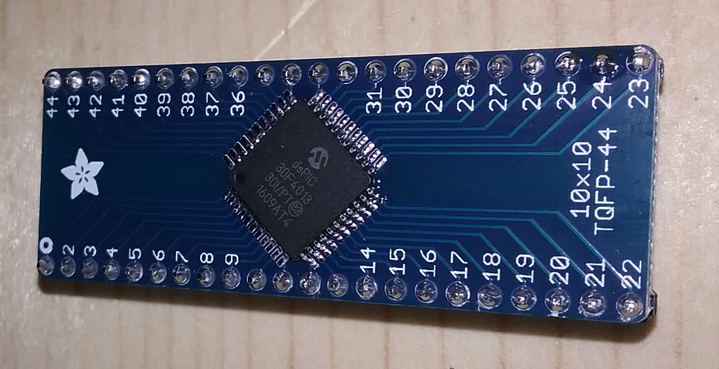
Not bad if I say so my self. And the best part: it actually works. Here’s a gratuitous shot of the new Rigol:
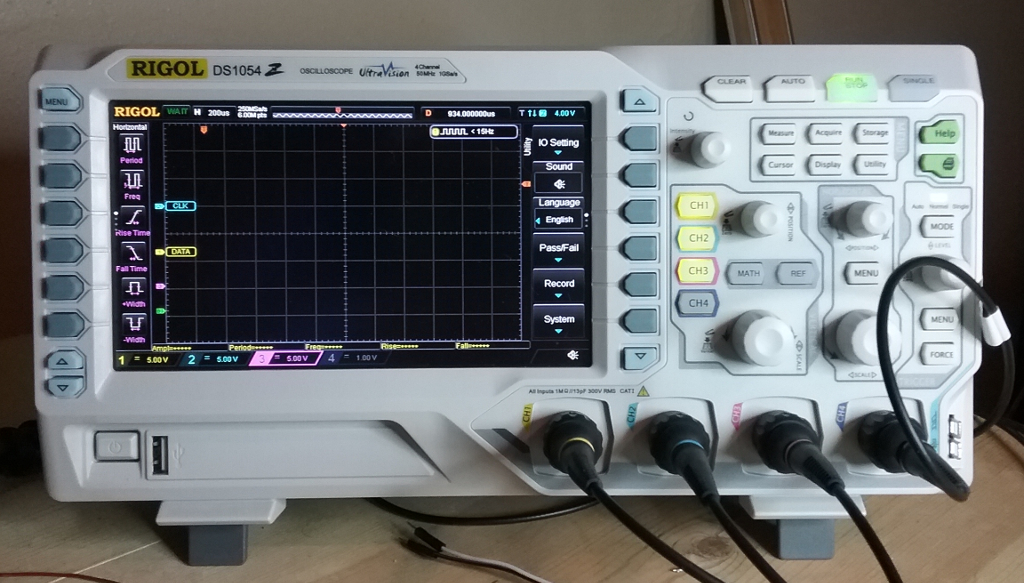
I gotta say that I couldn’t have done what I’ve do so far without that little bad boy. Here’s a scenario where it really helped me out.
I was debugging bulk read portion of the slave ISR. My approach to I2C is fairly vanilla: write a byte to a slave indicating the register and then either continue writing or reverse the bus and start reading. The first write though is critical as it tells the slave what’s the expected operation. Well the bulk write stuff was working fine. By bulk write I mean more than a single byte after the initial register byte. The bulk read stuff was returning only the first character of the buffer. In my implementation I have an index that keeps track of the offset into the data buffer and that index is incremented with every read or write. That index is reset every time an address byte is received by the slave or whenever the bus is reversed. Basically if I2CSTAT.D_A == 0, clear the index. Well that didn’t work as expected during reads from the slave because the D_A flag never went high! Which makes sense, I suppose, since the D_A flag represents the last byte received by the slave. The last byte that the slave receives, in a slave read scenario, is technically the address byte during a bus reversal. While technically correct, in my opinion it would be more in keeping with the spirit of the flag if it was reset after the first read from the slave. It would allow the slave to have some context in the ISR as to whether its servicing an existing or a new request.

So anyways, I was getting bogus reads from the slave. At the onset of troubleshooting I did not know if it’s the bus slave or master that’s screwing the pooch. Hookup the Rigol (I really need to name it) to the bus, enable decoding, and immediately see that the slave is sending garbage down the wire. Of course now I have an issue of how do you debug a timing critical service routine. It’s a classical manifestation of the observer effect. Just by looking into the ISR using my fancy new ICD3 (internet high-five!) I change the timing of the communication and everything goes to hell. What’s a boy to do.
But you see I have this fancy new oscilloscope. I inserted two lines in the ISR that blipped an output pin on the chip any time my buffer index was reset. To this pin I hooked up one of the channels of my scope. This allowed me to confirm that the buffer was reset to zero every time the ISR wrote out a byte to the master. While I probably could have gotten there without a decoding, digital storage oscilloscope, it would have taken much longer and been much more frustrating.
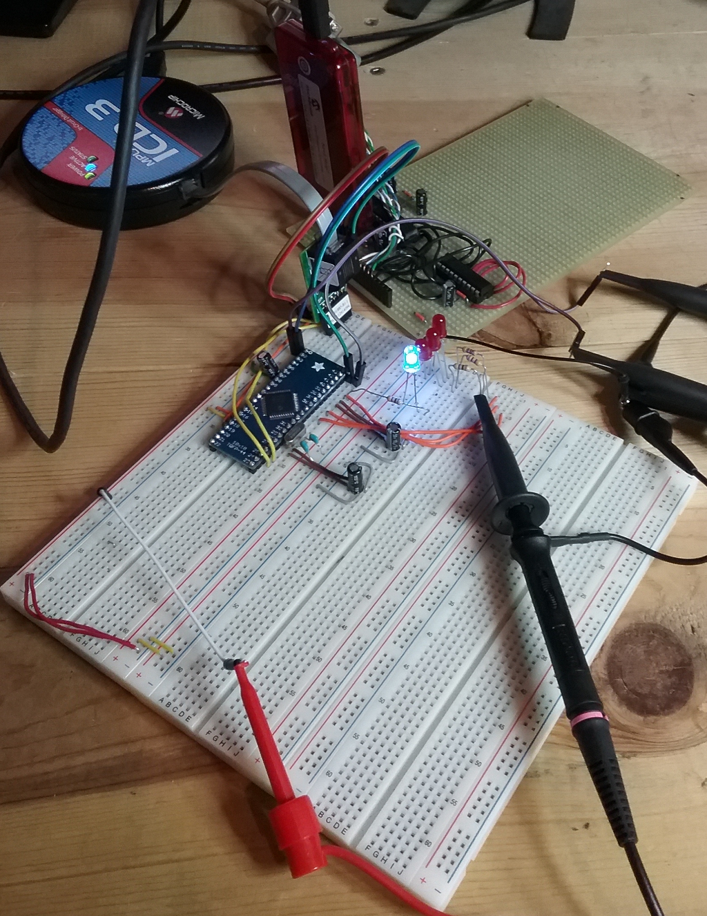
Here’s the setup as it is right now. The perf board in the back is from my experiments in the past. That’s the PIC24 and the MAX serial driver chip. Once everything is said and done those two chips, the dsPIC, and all supporting components will be on a single board.
In conclusion, I really enjoy this sort of development and troubleshooting. To me, developing on the micro controllers is almost zen-like. Yes it takes me a long time because I’m not an electrical engineer. I’d have to say that I spend about 90% of my time researching. But, and here I am about to throw more shit on the Linux ecosystem, the hardware community embraces and helps those who are less knowledgeable. The documentation of integrated components is thorough and detailed. It blows my mind that most documentation goes from the nitty-gritty details of operation like signal timings all the way up to complete sample circuits. Texas Instruments has a very extensive document encompassing the various circuits that you can use their opamps in. After reading a stack of manuals for the dsPIC30 line of processors, I feel like I come away from it more knowledgeable than I started.
Next step is updating the schematics to reflect the new variant of the dsPIC30 chip. After that it’s reading the ICTD sensors!