2019-08-26
2019-08-26
The VPSB (Vic’s Serial and Power Board) is functional. Fucking finally!
The last function to be tested was the current monitoring of the attached peripherals and I am glad to report that it works. Not flawlessly, unfortunately. I will have to replace the 0.010 ohm resistor current sense resistor with something a bit bigger on “production” boards. Going to try a 1.5 ohm in its place. With two 3 ohm resistors in parallel current sensing is working absolutely great.
Emulation of an I2C EEPROM chip is also complete. Other than displaying the board’s name during boot it does not seem to do much. I went through the trouble of implementing the brain dead pin configuration data and nothing seemed to change. I still need to play with it a bit more as the documentation is almost as brain dead as the design. It states that the specific bit maps have to be in big-endian format, but then includes the table in little-endian format. So who knows.
Below is a screen shot of the CLI session.
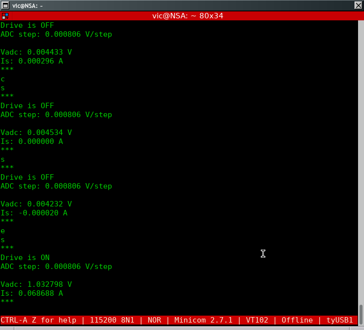
What we’re seeing here is the status right after microcontroller boot. The current sense is off by 296uA.
Next command is ‘c’ for … ‘calibrate’. Since we know the output is off, the reading should be zero.
Next two statuses are after calibration. First one is showing no offset while the second status is showing a 20uA offset. Not terrible.
Next command is ‘e’ for … ‘enable’ ( I really should get a prize for creative commands) which turns the output on.
Next command is status which shows that at the time that the CLI produced the output the current draw by the attached board was 68mA. This is relatively accurate as verified by my Fluke DMM. Because of the blinking LEDs on the IO board it’s a bit of a pain in the ass to get an accurate reading.