2018-11-25
2018-11-25
Long story made short, time has been scarce lately. School is sucking up most of my free time. BRCC math department stays true to its two principles: A) math was hard for me to learn and so it should be hard for you to learn and B) the championing of rote memorization over anything else. There’s an expectation of the the suckers students to memorize trig tables. Just mind-blowingly idiotic.
On to positive things. I have managed to make progress. Just sent off the BBB expansion PCB off to fabrication. Also ordered a reflow oven kit from Whizoo (http://www.whizoo.com/). I’m excited that soon I will be able to reflow a board without doing it one component at a time using a rework station.
The design of the current limiting implementation has been simplified significantly. My initial goal was to read the current at real time and adjust PWM drive to match the maximum current setting using a PID loop. I failed to make this happen. It came down to not being able to properly sample the voltage across the sensing resistor at low duty cycle conditions. With a 3.9KHz period, a 1% duty cycle on time is 2 usec. In that 2 usec the ISR has to get invoked, start the ADC sampling, finish sampling, convert the reading, etc. etc. I decided that given the amount of time that the system will spend in startup, it simply wasn’t a wise use of time to implement that particular approach. Instead, I increment the duty cycle something like 1% per second. Can’t remember the exact number right now. It works.
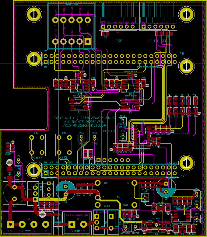
Below is the gratuitous shot of the layout. A lot of two pole test points have been added which should make it much easier to use the probe grounding spring. I took a bunch of scope screen shots with the grounding clip and had to throw them all away after going back and redoing them with the spring. The difference was night and day.
Next step is the BOM book keeping. Such joy.