2018-09-16
2018-09-17
With the gate driver IC and the MOSFET in possession, it was time to experiment. Below is a potato-cam(tm) pic of the layout.
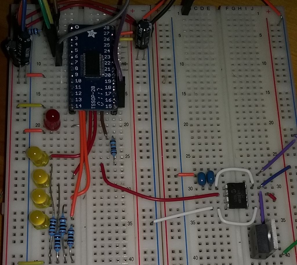
Fun fact: initially I forgot to hookup the ground on the gate driver chip and spend 30 minutes scratching my head. It’s hard being dumb sometimes.
So what we’re seeing on the right hand side is the 8 pin gate driver and below it to the right is the MOSFET. I am a super big fan of that Microchip TC4432 gate driver – simple, functional, good documentation.
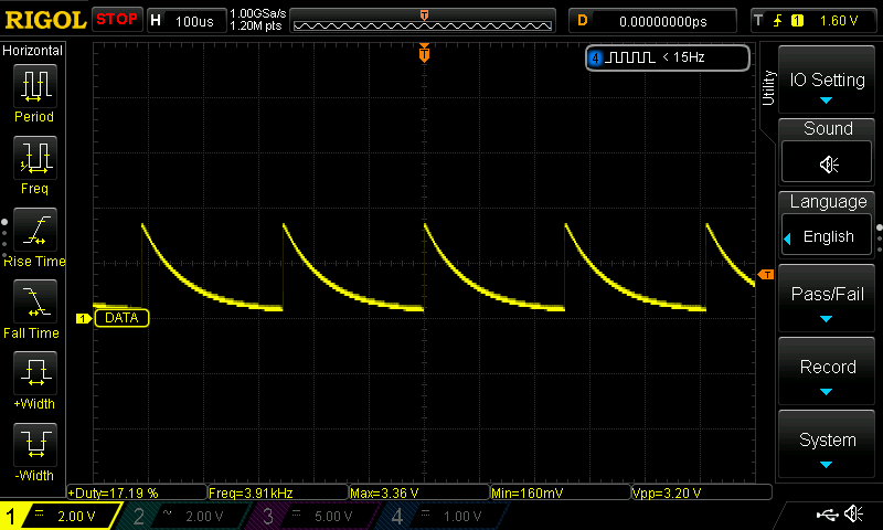
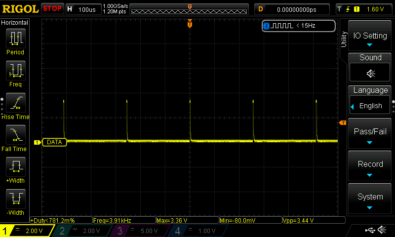
For fun I decreased the PWM period to 3.9KHz. Why? For funsies. Initially I started with 244Hz, but decided that I wanted to play with higher frequencies and since it’s my project I did exactly that. Here’s the rising edge of the FET gate as sampled at the gate driver.
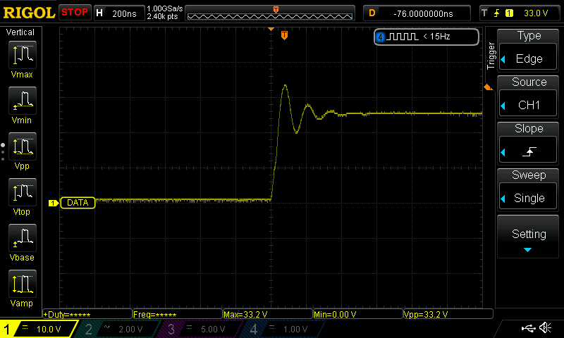
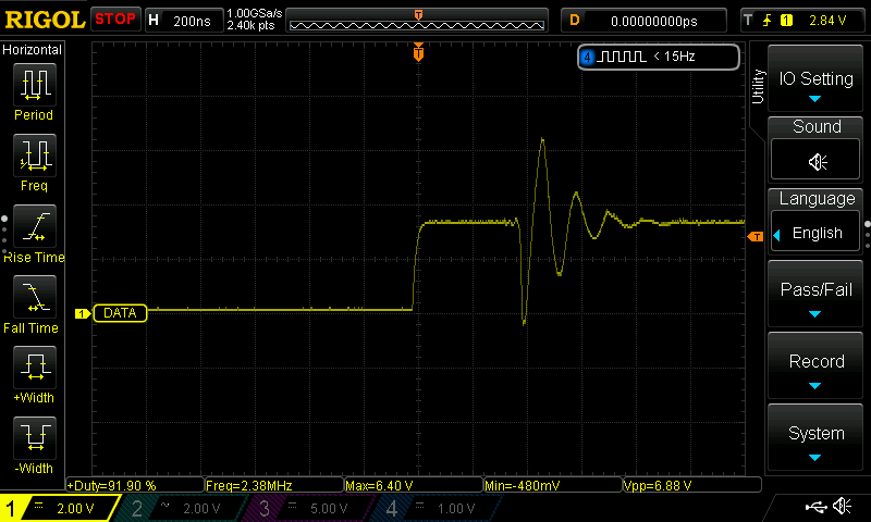
Very classic ringing waveform. Here’s an unloaded (gate driver disconnected) output from the PIC24
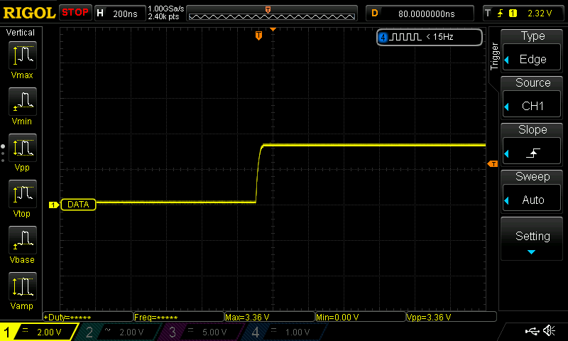
A super nice edge. Pornographic really. Here’s one with the output pin of the PIC24 connected to the gate driver with a 10Ω resistor inline.
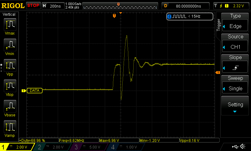
Less nice. Lots of inductive ringing. Vpp of 8.16V – ouch. That’s stressing something for sure. Lets see one with a 1KΩ resistor inline.
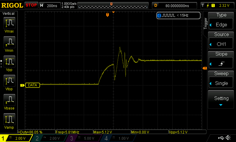
Slightly better, albeit a bit rounder (rounder is not bad!). Let’s see what a 10KΩ inline resistor looks like.
Oh sheesh. What happened there.
As I was writing this post I realized that something does not make sense on the brain level. Why is the 10K waveform so goofy? Went back to the scope and learned that the waveform above is sampled between the resistor and the gate driver. Here’s one that was sampled between the PIC24 and the resistor.
So that’s an interesting wrinkle. The higher the resistor value the more pronounced the difference between the gate side and the PIC24 side of the resistor. On the 10Ω resistor there is no appreciable difference.
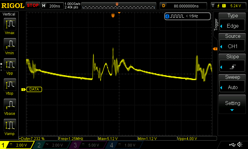
And as I was poking around, my probe tip slipped and made contact with the 24VDC pin and the input pin on the gate driver. I think I just blew the ass out on the PWM output pin on the PIC24. All of the sudden it’s putting out a saw tooth wave rather than a nice square wave. Probably blew bottom transistor on the push/pull circuit.
[Fast forward 5 minutes]
Confirmed. Without a pull down resistor
With a pull down resistor
Time for bed.