2017-08-15
2017-08-15
So it works. My IO board that has been in development for 7+ months works. The hardware works. Sure there are some warts that need to be addressed in revision C, but it works. It is functional. The firmware works. The CLI-style human interface works and the binary machine interface works. Sure there are some warts, but it works. The Linux portions, the multi-threaded, multi-process, bi-directional serial stack, and misc works. The human interface component that talks to the lower level stack works. It only took two weeknights to be fully integrated throughout the stack and fully functional. It has warts, it needs refinement, there are experimental bits, but it works.
This is the Qt-based HMI component. It communicates with the middle layer – the piece that will eventually be the logic/PLC thing. The goal here was to test the integration of the three layers – the human interface, the driver/communications/logic layer, and the hardware layer. It all works.
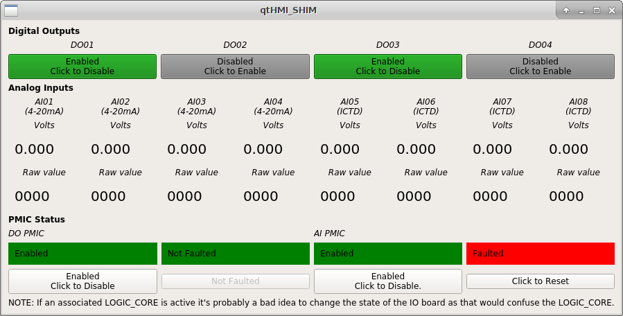
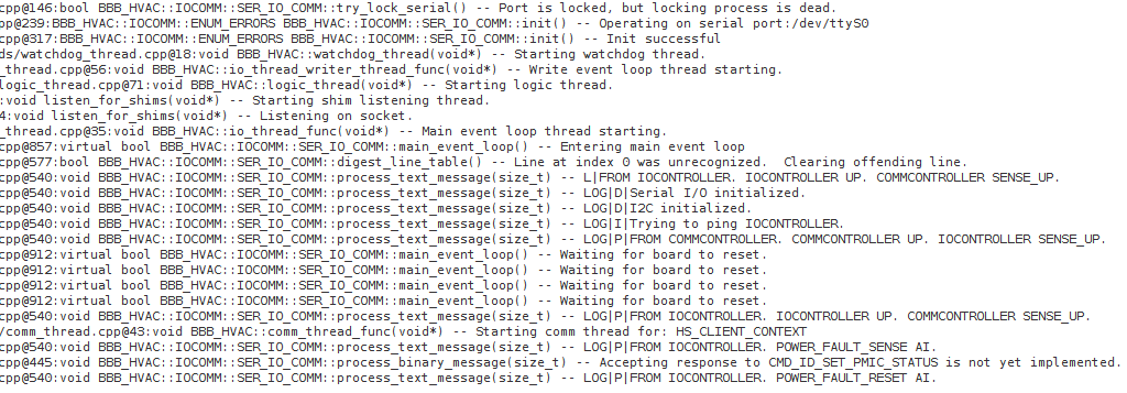
This is the log output out of the middle layer. It does not mean anything to anyone except for me. What we see in the last few lines is me tripping the analog input power management IC (PMIC) by placing a jumper across screw terminals and then resetting the fault using the HMI.
What’s next is that I have a few things to address in revision C. Below is an approximate list of items to be addressed. Over all very few serious items.
- Analog power output reset switch label inconsistent – verbiage change.
- Reorder the caps in order of capacity – this is to make assembly easier. Right now the caps of all capacities are all over the place. I will rearrange them so that they are in order and also grouped. If nothing else it will be more aesthetically pleasing.
- Convert LED resistors to SMT – unavoidable really. In order to make maximum use of the board I am forced to use both sides of the PCB.
- Remove chip sanity ICs – this was a bit of a fuckup on my part. Need to do much more research before next attempt.
- Add pull-down resistors on the PMIC enable line – I just keep not learning my lesson – more resistors = more better.
- Add ICSP header holes in addition to the RJ12 jack – this will enable programming the board without installing the gigantor RJ12 jack onto the board.
- Jumper for board-wide reset button – will separate the reset lines on the two microcontrollers. Purely a luxury item.
- PMIC fault output cannot drive LEDs directly. This is a fun one that I would have caught had I properly prototyped the circuit. Apparently the fault output on the PMIC can only provide up to 100uA at 15V or something equally silly. I had a voltage divider driving an LED and a pin on the IO controller. The LED would light, but the microcontroller would not recognize the input as going high. The micro has a Schmitt trigger on the input which requires 0.8VDD to trigger. With the load of the LED the fault output would not get up to the required voltage. The trigger voltage was 4-something and the fault output would get driven to something like 3 volts. I can’t remember the exact numbers. Leave me alone. Point is the LED and the fault output will have to be separated and two extra pins on the IO controller will have to be dedicated to driving the fault indicator LEDs.