2017-08-05
2017-08-15
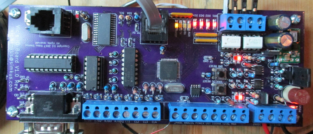
Revision B of the board PCB came in and has been assembled. All of the issues from revision A have been addressed. Did find a couple of issues in this revision though.
- I added microprocessor sanity checking circuitry and IC. It does not work at all. On the PIC24 it keeps rebooting the chip on the dsPIC30 it prevents the ICD3 from connecting to it. I will be ripping it out in rev C and just wiring in a standard board reset button. This is what I get for not prototyping a circuit before incorporating in the design.
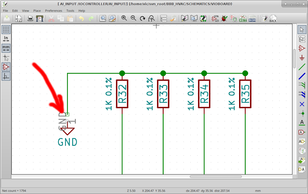
- Due to an unnoticed broken wire in the schematics (see below) the ICTD input resistor were not grounded. This sucks. Apparently this is not a DRC error in KiCad.
- I reversed digital output indicator LEDs for outputs 3 and 4. Not even gonna try to attempt to explain that brain-fart.
Screenshot of the broken wire that’s not a DRC error.
Some pictures of rev C. I simply cannot mange to take a decent picture. I don’t understand why everything looks ‘dusty’.
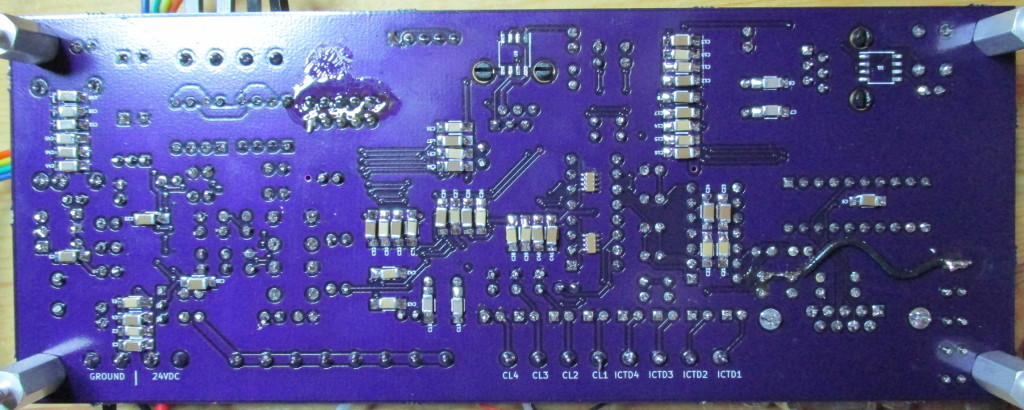
Notice the bodge wire in the lower right hand corner. This is to provide a ground for the ICTD input resistors.
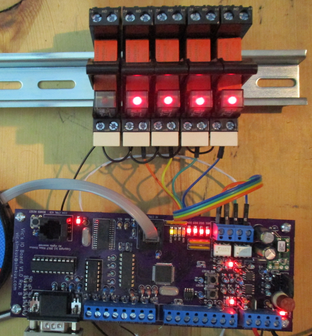
It actually works. All of the digital outputs work and (out of shot) analog inputs are operating as expected.
So funny story. I replaced most of the fuses from rev A with two current monitoring ICs. One of the digital output and one for the analog sensor output. I was testing the analog circuit protection functionality by shorting the protected 24VDC output into the analog input. The purpose was to simulate a sensor failing shorted. The analog input is supposed to be able to handle the over-voltage by dumping into the 5V rail just long enough for the overload circuitry to trip. Welp I accidentally applied the “unprotected” 24VDC directly from the power supply to the analog input. A spark was seen, my test lead spot welded to the input terminal, and the power supply shutdown on overload. This is all inside of a second. The power supply was set for 1.5A over-current protection, but that was a touch too high. The clamping diode gave up the ghost and I think that the input controller (dsPIC30) got its brain scrambled in a very funny way. It seems to run fine, it can be erased and programmed by the Microchip IPE and MPLAB X, but it’s device ID apparently got screwed up.
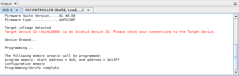
The ICD3 is not the problem since it works just fine with the PIC24.
Oh I also blew up my Beagle Bone Black a few days ago by applying 5VDC to connector P8 instead of P9. Oopsies.