2018-08-04
2018-08-04
Been working on the software side of things. The goal was to put together a logger for all of the sensor data. For that I had to make logic core expose all of its various values. Not a super huge deal, but had to remember the code base from 6 months ago. Document your code, kids.
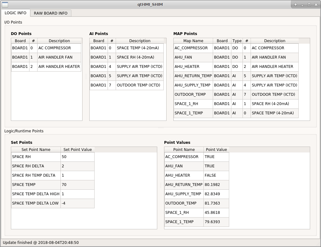
Below are a couple of screen shots of the qtHMI_SHIM which is my playground and reference implementation for all communications protocol stuff.
Here we can see all of the various points and their mappings. DO are digital outputs. AI are analog inputs. Map points map a mnemonic that the logic core uses in its processing to a physical point on the board. Point values are the actual calculated and converted real-time values within the logic core. For example, we see that AC_COMPRESSOR is TRUE (meaning it’s on), that the AHU_FAN is TRUE (also on), and that SPACE_1_TEMP is approximately 80F. Everything is fairly self explanatory.
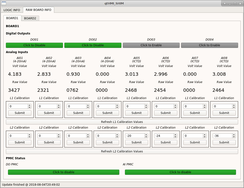
Below is the actual physical state of the board. We see the raw ADC values, the resultant volts, and so forth. The ICTD inputs have L2 calibration values because I went through and calibrated the three inputs against a cup of ice water. The most extreme correction is on analog input 8 where I had to adjust the ADC value down by 36. Perhaps not coincidentally this is the input where the least significant digit flutters between 1 and 2 with nothing connected to the terminals. This will be next area of investigation.
That’s it for now. Solid progress is being made.