2017-02-17
2017-02-17
This update has been a while in the making. Between the last update and this one I accidental adopted a dog.

That little shit machine has been a time sink.
The Hardware Portion
So anyways, the previous objective was to interface the NASA quality 4-20mA current loop simulator with the BBB. Several related and unrelated issues had to be address
- A bit tangential, but the GPIO pins are high when the BBB is first turned on. That means that everything that it controls would be on until the boot process finished and the pins were configured. This sucks because what that means in practical terms is that 1) heater 2) fan and 3) AC compressor would be on until the boot process finished. This is a behavior that will be desired later in the project, but for now that’s bad.
- The docs for the chip specify that no voltage is allowed to be applied to the pins until after the reset pin (SYS_RESET) goes high. So that means that I need to be able to switch on the 24V power rail (feeds the 4-20mA sensors) explicitly at a proper time.
- The third issue I believe is due to a substandard initial fix for #2 above. After I implemented 5V and 24V rail switching using a gob of transistors I was still getting a ‘blip’ on both power rails when I powered on the BBB.
Issue #1
Couple possible fixes for this one.
1. I could have used PNP transistor to drive the stuff hung on the output pins. During the booting process, the pin would be high which would not bias the transistor and thus the doohickey being controlled would not be on.
I didn’t like that one because to in my mind a pin being high (3.3V) is a logical ‘on’ while it being low (0V) is a logical ‘off’. This seems pure to me. Driving the pin low to turn on doohickey gives me flashbacks of working on certain Japanese process equipment that had the ‘sinking’ output on a PLC. It felt wrong and it is wrong; 1 = ON, 0 = OFF. Period. Sinking outputs are un-American.
2. I could have used some sort of a bus switch.
I didn’t like that one because I didn’t know about them at the time. Given that I know about them now, I still wouldn’t choose them. One reason is that they’re kind of whimpy.
3. Optically isolated SSR to switch the power rails. The idea being that a set of SSRs switch the 24V and 5V power rails on after the chip boots.
This is definitely the right choice. First: Optically isolated. Optical stuff is one step away from lasers. Lasers are cool. Therefore optical stuff is cool. Second: SSR are also cool. I still have that one PNP transistor (to switch on the SSR) dangling there like a hemorrhoid, but hey – we’re all making sacrifices.
Issue #2
This dovetails with issue #1. A sensor can’t supply voltage to the chip if the sensor is not receiving any power.
Issue #3
Once I got rid of my amateur-level gob of transistors the blipping issue went away.
The SSR relay I used is the Toshiba TLP222A-2. The turn on current is 3mA and the on-state resistance is 2 Ohms. Perfect for my application. Currently I’m turning the relay on and off using a GPIO pin. I could wire it to the reset pin and turn both rails on when it goes high, but then I’m back to issue #1.
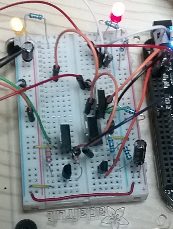
This is the concoction before the SSR. Fucking potato of a camera.
This is after the SSR:
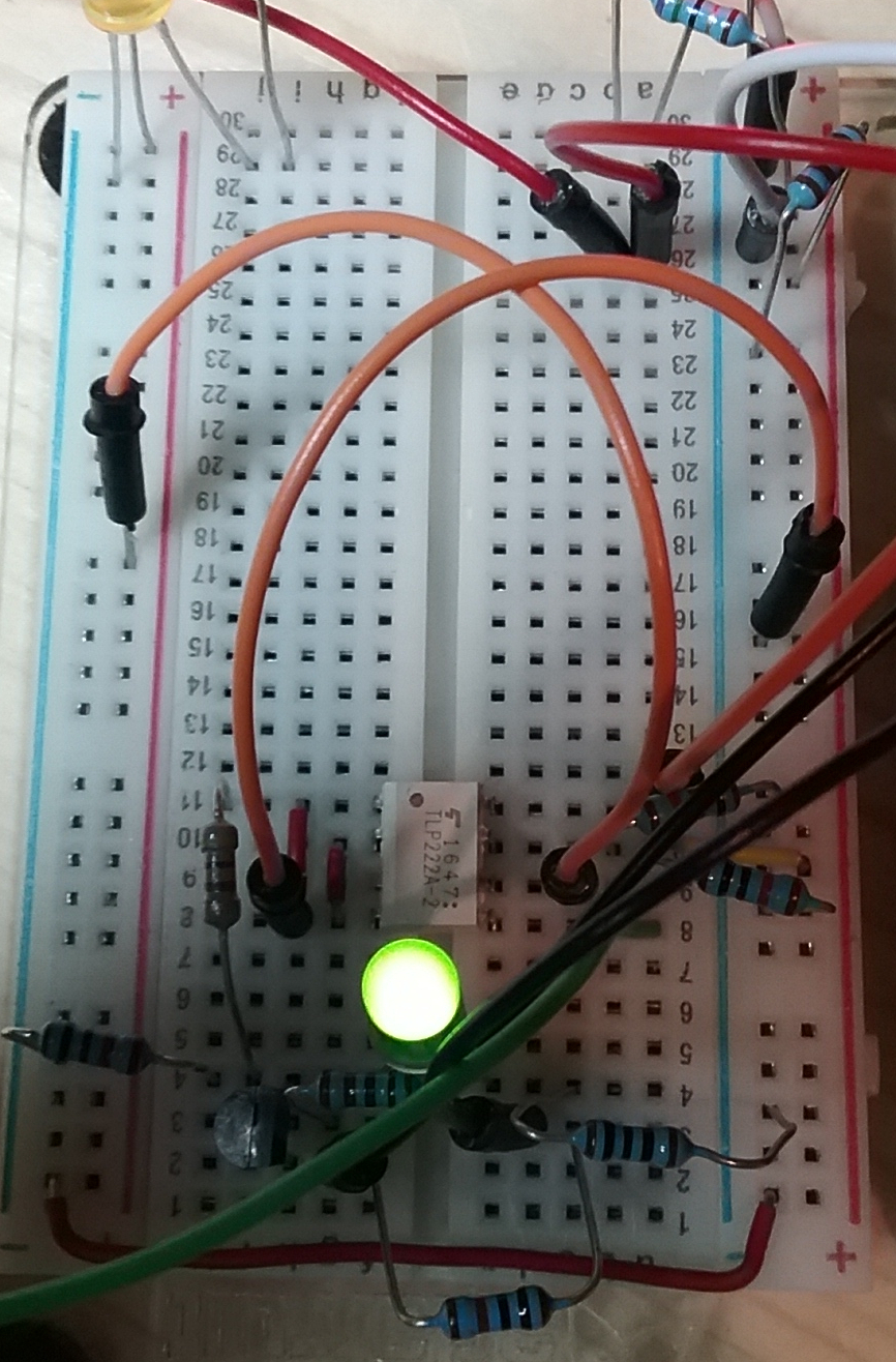
An SSR, couple resistors and Bob’s your uncle.
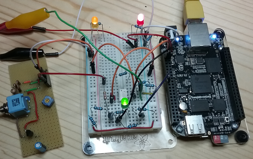
Here’s the complete setup with both 24V and 5V rails and the current loop simulator:
The Software Portion
I have several goals for the software and my inability to find any off the shelf solutions that meets the criteria is one of the catalysts for this project.
- Completely standalone with no external dependencies. I don’t want something that has to rely on “the cloud”, “SaaS”, “ASP” or anything else that stands for “someone else’s computer”. I neither want a subscription nor do I want a compromise vector by letting some third party into my home network.
- Complete separation of the logic and human interface. The human interface is generally the most complicated piece of software. I do not want my AC system going down because a display driver IC shits the bed or some spaghetti code UI code crashes the system. On a side note, I will be putting this project on Beagle Bone Green before going live since it dispatches with HDMI.
- The software itself needs to be simple. No external dependencies outside of the OS and the standard C/C++ libraries.
- Nothing JavaScript or whatever the current flavor of the month stack is. All C/C++ all the time, baby.
- Every piece of software that’s related to the project must produce no warning in Valgrind Mecheck and Helgrind (http://valgrind.org/info/tools.html).
With that being said I have the following pieces running in test:
The server
I started writing this in C, but quickly moved to C++. Raw C was a bit much for all reasons that C is known for. The server will communicate it’s status and accept commands via a Unix domain socket. It is multi-threaded and can service multiple clients at once. Each client gets its own thread and the logic is performed in its own dedicated thread.
The server does no authentication or authorization leaving that to the client. The server is implemented with security in mind from the ground-up. It will not run as root, is limited in scope and functionality, and is not exposed to the outside world.
In reality this really should be renamed as the title server has functional implications.
The client
Communication with the server is implemented, but everything else is only stubs. The idea is to have a text client accessible via SSH and some sort shim that speaks to a fancier HMI such as a touch screen display via TCP/IP.
This piece should also be renamed as its function is not exactly a true client.
Next step is to hook up real output modules. Have those on order and they should be here Saturday.