2017-01-18
2017-01-18
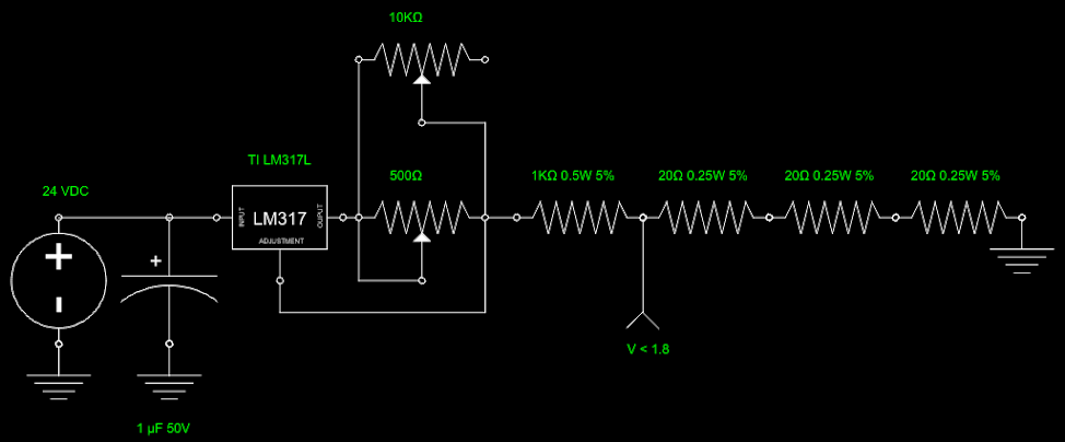
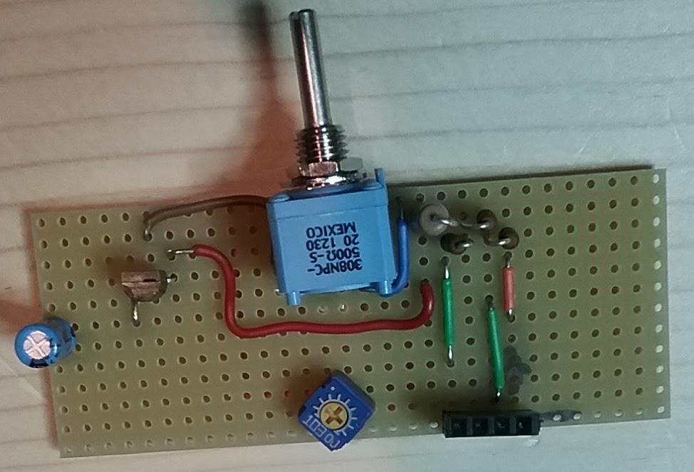
The 4-20mA current loop simulator is done. Pictures of the finished product below. Most of the parts I had on hand, but did have to buy a regulator (Texas Instruments LM317L) and a 500 Ohm 0.5 Watt pot. The pot was a shocker – approx $12. I usually buy quantity 10 of whatever I order just to have it on hand, but this was an exception.
The above was designed (and boy do I use that term loosely) with three resources: 1) Google 2) Google 3) product docs 4) trial and error. I believe the initial idea came from allaboutcircuits.com (http://allaboutcircuits.com). That site is a wealth of information. Between them and the EEVblog (https://www.eevblog.com/) I’m fairly sure that even an average idiot like me can build … something complicated.
I made a decision to use 24VDC for the 4-20mA sensors. No reason other than I’m used to that from my industrial controls experience. The voltage divider resistor weirdness is due to me having those resistors on hand and a need to sink 20 mA in such a way that I get less than 1.8 volts to feed into the BBB.
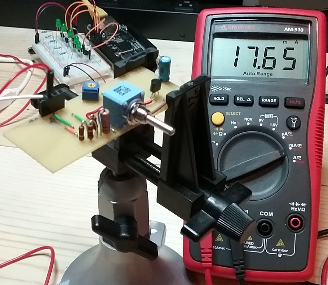
The 10K pot is there for trim/adjustment. With the circuit without it I couldn’t quite get down to 4 mA. With it adjusted to just shy of 1K, I get a nice solid 4 mA. I did the math and then immediately forgot it, but with the 500 Ohm resistor and the pot adjusted to just shy of 1K, the two resistor in parallel come out to 300something Ohms.
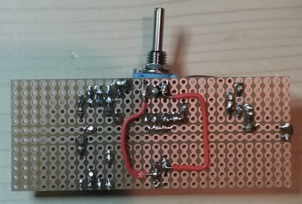
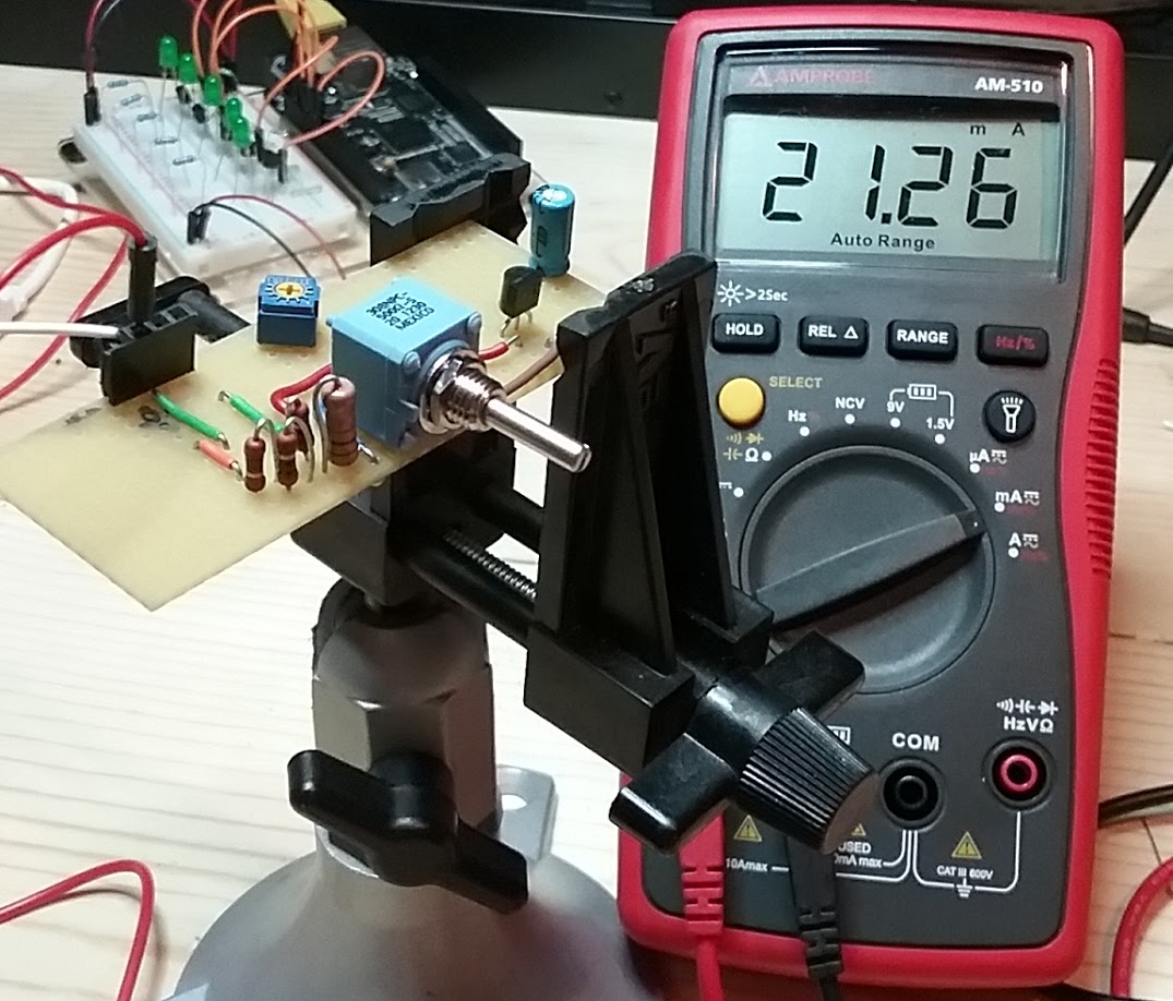
Here’s the completed item on a proto board.
And here it is in action.
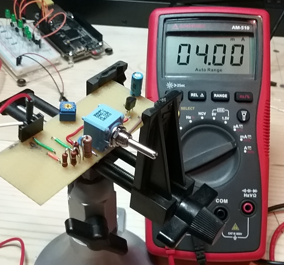
The camera on this phone is just dog shit.
Next step is to interface this current loop simulator with the BBB in such a way as not to blow a chunk of the CPU off.