2017-01-08
2017-01-08
The Software
So the next goal for this project was to get the BBB (Beagle Bone Black) to be able to drive digital output and to setup the reading of values from a 4-20mA current loop. Googling on configuring a GPIO pin to output with pull down resistors sent me down the rabbit hole of Device Tree overlays, kernel drivers, subsystems, SysFS, and so forth. Spent two days in the fuckery that is Linux documentation and blogs from 2013. The best way to describe Linux kernel documentation is:
The blogs were naturally out of date since anything that is older than a month is considered obsolete in the Linux world and more than likely has been changed if no reason other than it’s older than a month.
Somehow I came about a set of precreated overlays and their associated utility – config-pin. And then there was light. Now all of this applies to my system:
Linux beaglebone 4.4.36-ti-r72 #1 SMP Wed Dec 7 22:29:53 UTC 2016 armv7l GNU/Linux
If it will be applicable in a month is anyones guess.
Under /opt/source/beaglebone-universal-io lives a set of overlays and a cheeky little file README.md. Quote:
This project is a series of four overlay files, designed to work with
the BeagleBone Black:
* cape-universal Exports all pins not used by HDMIN and eMMC (including audio)
* cape-universaln Exports all pins not used by HDMI and eMMC (no audio pins are exported)
* cape-unversalh Exports all pins not used by eMMC
* cape-unversala Exports all pins
* cape-univ-emmc Exports pins used by eMMC, load if eMMC is disabled
* cape-univ-hdmi Exports pins used by HDMI video, load if HDMI is disabled
* cape-univ-audio Exports pins used by HDMI audio
Could it be… It was! Precreated overlays that do exactly what I am looking for. Since I want to keep intact the HDMI and eMMC the cape-universal is my overlay.
On my system the cape manager SysFs directory is /sys/devices/platform/bone_capemgr. Lets see if we can make this thing do our bidding.
root@beaglebone:~# cd /sys/devices/platform/bone_capemgr/
root@beaglebone:/sys/devices/platform/bone_capemgr# cat slots
0: PF---- -1
1: PF---- -1
2: PF---- -1
3: PF---- -1
root@beaglebone:/sys/devices/platform/bone_capemgr# echo "cape-universal" > slots
root@beaglebone:/sys/devices/platform/bone_capemgr# cat slots
0: PF---- -1
1: PF---- -1
2: PF---- -1
3: PF---- -1
4: P-O-L- 0 Override Board Name,00A0,Override Manuf,cape-universal
root@beaglebone:/sys/devices/platform/bone_capemgr#
Finally. Progress! Word of caution. Unloading this cape causes the system to crash:
root@beaglebone:/sys/devices/platform/bone_capemgr# echo "-4" > slots
Message from syslogd@beaglebone at Jan 1 00:07:45 ...
kernel:[ 111.235220] Internal error: Oops: 17 [#1] SMP ARM
Message from syslogd@beaglebone at Jan 1 00:07:45 ...
kernel:[ 111.353070] Process bash (pid: 2388, stack limit = 0xdb54e218)
Message from syslogd@beaglebone at Jan 1 00:07:45 ...
kernel:[ 111.358944] Stack: (0xdb54fb60 to 0xdb550000)
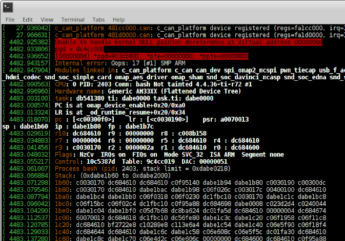
Oops indeed.
In order to persist between boots (remember that I ripped all of the systemd crap off of my BBB) I added this to the /etc/rc.local
echo "cape-universal" > /sys/devices/platform/bone_capemgr/slots
The Hardware
More blinking lights is more better. Everyone knows this. The final product will have LEDs and relays driven by the BBB, but for testing purposes we there’s only LEDs. Here’s the pin assignments I am using:
| BBB Pin |
TI Processor GPIO |
Linux GPIO |
| P9.11 | GPIO0[30] | 30 |
| P9.12 | GPIO1[28] | 60 |
| P9.13 | GPIO0[31] | 31 |
| P9.15 | GPIO1[16] | 48 |
| P9.17 | GPIO0[5] | 5 |
The output is basic. Controlled circuit: Vdd – resistor – led – transistor(collector). Controlling circuit: GPIO – resistor – transistor(base). The transistors I used are STMicroelectronics STPSA42. I’ll make a diagram some other time. The LED/Vdd resistor is 75 ohm 1%. The GPIO/transistor is 2.2K Ohm 1%. I went through and measured the voltage drops across all of the resistors out of curiosity.
75 Ohm Vdd/LED Resistor
| V Drop |
Current |
| 2.30 | 0.031 |
| 2.28 | 0.030 |
| 2.25 | 0.030 |
| 2.38 | 0.032 |
| 2.37 | 0.032 |
| Total: | 0.155 |
2.2K Ohm GPIO/Base Resistor
| V Drop |
Current |
| 2.54 | 0.001 |
| 2.54 | 0.001 |
| 2.54 | 0.001 |
| 2.53 | 0.001 |
| 2.53 | 0.001 |
| Total: | 0.005 |
So a total power draw of 0.160 amps or 160 mA. My cheep hobby-level DC power supply display showed a draw of 240 mA with all of the LEDs turned off and 400 mA with all of the LEDs turned on. The difference is of course 160 mA which jives with the calculations above. Given that I’m using a 15 year old Craftsman DMM and a $90 power supply I am very satisfied with the results.
Here’s the setup as of right now.
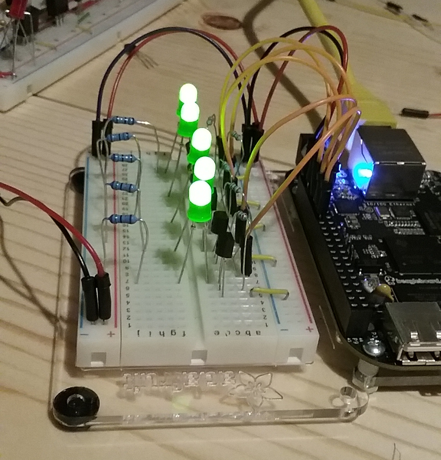
Next step will be to cobble together a 4-20mA current loop simulator.