Vic’s IO Board V1.0

The Why
It all started with a thermostat. As in I wanted a new one (See here). Because I am super special little snowflake, none of the thousands of thermostats on the market suited my needs. The initial inspiration is well documented; I will not waste time repeating myself.
So I needed a way for the control logic to interface with the physical world. This of course is done via an IO board and there seemed to be two options – the industrial-level stuff intended to be used with PLCs and the amateur “arduino”-level stuff that’s available everywhere on the internet for less than $20.
The cover for the first party is in the 5 digit range even if you manage to get an invitation. The other party is one guy with a funnel looking for someone with a keg. I wanted to be in the fancy party, but did not have the money nor the invitation to get in.
So I decided to put my experience gained through being a bartender at the fancy party into an IO board of my own. That’s enough analogy maceration.
My goal was to have a robust IO board for my personal project(s). I wanted the board to:
- work on 24VDC
- minimize the impact of human error by having protected inputs and outputs
- be a coherent package
- be as easy as possible to troubleshoot and integrate
- have some level of support by the manufacturer
Basically, I wanted a robust piece of gear and since I couldn’t afford one I made my own.
The What
The board, in its current V1.0 incarnation satisfies most of my requirements. Only thing lacking is support from the manufacturer. It’s a hassle. They’re real moody pricks.
Board features and specs:
- Dual micro-controllers
- Dedicated communications processor
- Dedicated input/output processor
- 24VDC power supply
- Fused
- Reverse polarity protected
- Over-voltage protected via crowbar circuit
- ESD protected
- Analog sensor power supply
- Over-current protected with software detect and reset
- Diode-protected output
- Eight analog inputs
- Over/under voltage protected
- 12-bit resolution
- Four ICTD inputs that can double as 0-500mV inputs
- Four 4-20mA inputs that double as 0-5VDC inputs
- Adjustable low-pass filter on the analog inputs
- Four digital outputs
- Over-current protected with software detect and reset
- Sourcing configuration
- Diode-protected output
- Communications
- RS-232 signaling
- Hardware (CTS/RTS) flow control
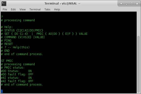
- Text-based interface intended for human use
- Binary interface intended for machine use
- Firmware
- Mostly C code written with explicit goal of not being unnecessarily clever and hard to understand
- Minimal assembler. Some assembly is present on the account that it is unavoidable and C inline assembler is ugly.
- Thoroughly documented
- No external dependencies
- Open design
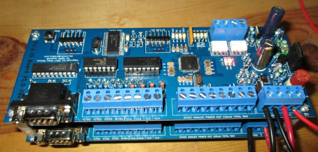
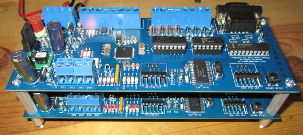
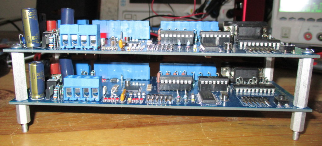
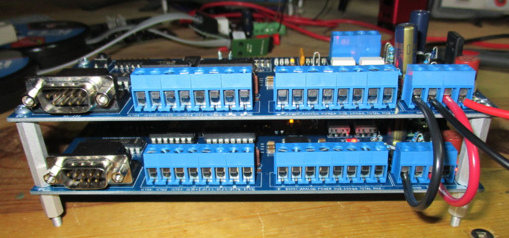
Bellow is a few pictures in the dual board configuration. Why dual board and not two, three, or four? Simple. Because I am the decider and I decided.
Click on the pictures to expand them.
Top view
Another top view
Dual stack – digital output terminals
Dual stack – RS-232, analog input, analog power supply, and power supply terminals
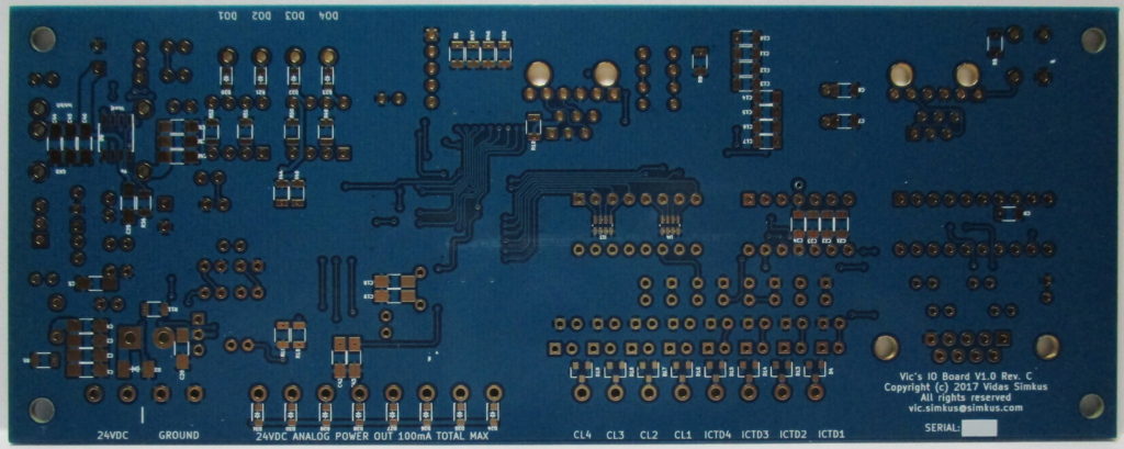
Back of the PCB
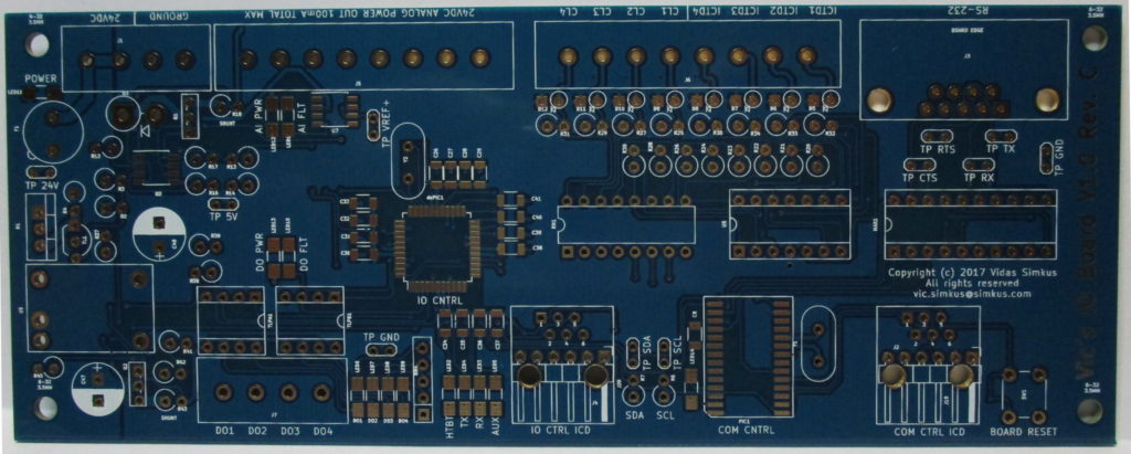
Front of the PCB
Text-based interface intended for testing/human use